• You are viewing the forum as a Guest, please login (you can use your Facebook, Twitter, Google or Microsoft account to login) or register using this link: Log in or Sign Up

How to use a PLC to control your fish tank.

The logo8 software is pretty easy to learn as well IMO. Plus has great simulation mode too. Once i fitted mine in tanks cabinet which i did with ethernet over mains at the same time, uploading software changes takes few moments. Real time monitoring too.
Then built in data logger so you can upload over LAN or microSSD and check its all working as designed. Mine even records how long it takes to get to target pH. Then turns off booster CO2 injection and trickle CO2 injection takes over. (Duel CO2 solenoids) instant lights at press off icon on phone or extended moonlight period. Turns independent pump off for quiet evening viewing. Easy printout off all timer settings. Adjust timmers easy at comfort of PC/laptop or even mobile phone if you do ( or copy) a software like Ian's.
Think the PLC is the DBs

Sent from Mountolympus via neural interface
 
I had never used logic before I used the software, pretty straight forward.
One app/game I have come across on my phone is 'Curcuit Scrabble' simple game that gets you to understand the use of the some of the logical blocks that the PLC software uses.

Sent from Mountolympus via neural interface
 
Zeus PLC Build (summary) will add links when I have time

I was after a unit that would turn lights on and off and also dim the Four kessil A160 that I had purchased. The Kessil Lights dimmer function works on an Industry standard of an analog input 0-10V controlling the Lights Intensity and spectrum so I needed two analog outputs in the 0-10V range.

Plus one feature I came up with that I fancied was the Moonlight Passover phase. Where one kessil would be on its lowest setting at a time for 10-20mins each. Thought it would look great. The issue with this is that the Kessil 160 pass on their analog 0-10V input only when the power is on the Kessil light. I could leave the power on and just use eight different 0-10V inputs but that would of needed four Siemens LOGO! 8 AM 2 AQ at £100 each. So I decided to wire the analog inputs in parral to the Kessils and then have the PSU for each kessil on a timmer. So Four Outputs need for kessils.

The T5 Ballast I have has two plugs on it one for tubes 3&4 and another for tubes 1,2,5 &6. So two outputs needed there.

One for pH controller power, Plus two for the Twin solenoids I have for duel CO2 injections, one for booster period other for maintaining pH drop so three for CO2 control.

One for Filter

One for twin heaters

One for Ehiem 3000+ which is on an independent loop to maintain good flow and for CO2 booster injection.

One for Air pump

Three for auto dosser - Macros. Micros and LCO2

One for fish feeder

So 17 outputs needed. The base unit has Four outputs and expansion modules come in four or eights.

So went for 20. Auto top up was an option at the time, but with hooded Rimmed tank water loss isn’t an issue

I was after controlling when the heaters came on and off also so two choices with the PLC

Siemens LOGO! AM2 RTD plus PT100 – large linear temp range very accurate but costly.

Rugged Vinyl Tipped Thermistor Sensor which with a bit a soldering resistor and capacitor could give a 0-10V input to the PLC base unit and measure the temp in a non linear way is a less accurate way- but accurate enough IMO.

So a choose the later.


upload_2017-5-25_19-57-7.png

So the PLC just monitors the volts bit of programing set your on off values and heaters on and off Via PLC, just set the heaters at slightly higher temp and failsafe.

upload_2017-5-25_19-57-43.png

Plus I Have added a slightly lower temp for night time, plus heaters off during initial CO2 booster period.

I have yet to Fit the Sensor as it was last on my list, ordering Friday.

So orderd ( well messed up order a few times but got therein the end)

LOGO! 12/24 RCEo, LOGO! Power 24 V, 1.3 A, LOGO! TDE

LOGO8 DM16 24 R (x2)

AM2 AQ expansion module, voltage supply: 24V DC, 2 AO (Analogue Outputs), 0-10V, 0/4-20mA.

The total width off the PLC was 305mm. after much looking around went for TK PS Plastic Enclosure, IP66, 360 x 254 x 111mm From RS with 220 x 331 x 2.5mm Mounting Plate for use with TK Enclosure
But it was still going to be tight. And wire manament wasn’t going to be easy I bigger Enclosure would off been better for wiring but too big. So leap of faith required.
I wasn’t going to be able to wire it like I had thought so raised the 35mm Din rails and ran wire under Din rail
upload_2017-3-16_20-42-37-png.104357


so
upload_2017-3-18_13-45-49-png.104371
upload_2017-3-18_13-47-35-png.104372

and just fit
upload_2017-3-18_13-52-28-png.104375


Little on tight for room for switches

upload_2017-3-18_13-57-25-png.104376


20 socket output MDF

upload_2017-3-17_12-44-16-png.104365


About this point I decided to put the PLC enclosure on the side wall off cabinet.

20 live wires to get from enclosure to outlets plus neutrals and earths. So decided on ring for neutrals and earth then separate live feeds.

Used the Fluval FX6 piping and a Gland

upload_2017-3-21_18-20-51-png.104446


Then found out the entry point for the wire to the PLC enclosure wasnt going to work

wired up my monmentory push switches off ebay and some very nice locking swicthes of Ian he had left over :thumbup:

upload_2017-3-25_14-47-53-png.104501


Raised the Lower DIN rail on Left hand side so wires to outlets could be passed in.

upload_2017-3-25_14-49-1-png.104502


The enclosure had to be fitted in the cabinet before the DIN rails

upload_2017-3-26_16-21-28-png.104523


Was a little tight for space but got it wired up. Uploaded my software and was working

View attachment 104605

To date the legend for the inputs and outputs is

upload_2017-5-25_20-11-51.png


This took quite soon time to decide and work out, but its working great but not finished.
Ian_m has been a massive help with daily multiple PM at times going back and forth since October 2016. I cant thank Ian enough for his MASSIVE help and patience:thumbup: :clap:
 

Attachments

  • upload_2017-5-25_19-25-51.png
    upload_2017-5-25_19-25-51.png
    91 KB · Views: 388
  • upload_2017-5-25_19-26-12.png
    upload_2017-5-25_19-26-12.png
    54.1 KB · Views: 391
  • upload_2017-5-25_20-3-58.png
    upload_2017-5-25_20-3-58.png
    50.3 KB · Views: 405
Last edited by a moderator:
Ian / Zeus,

How valuable is having the display on the PLC, I notice that there are units available without it.

Cheers.
 
I got the lcd version of the plc for the following reasons:-
- You have manual control of stop/start, as well as simple programming.
- You can edit the blocks in your fbd, eg alter on/off times.
- Can display status of the inputs, handy for debug.
- You can have the display show a status of what it is up to eg, co2 on, wave on etc.
- You can change background colour to orange for say a warning, in my case something changed or red as warning, in my case main filter or heater off.
- In your fbd in conjunction with the keys you can allow settings to be altered easier than the plc setup menu. See my code.
- I wanted the ability to edit settings say during weekly water change at the tank rather than having to alter settings using a phone or pc.
 
Well I think our opinions would be different on that one. Ian has done a fantastic job on his software so he can edit the settings for timers etc it from the screen. Plus he can see his screen. I cant see my screen easy, but I have done mine connected over the LAN. So I just use my PC to edit the settings or use my Phone to see whats going on. All the settings can be done Via the PC I think the only one I did via the screen was set its IP addresses, but I would off thought you would just need to set your PC/laptop to the same default gateway as the Base Unit then your would be able to connect to it then change it to the Normal default gateway you use at home. Press OK change your PC/laptop address back and you should be able to access the base unit again.

upload_2017-5-27_17-10-58.png


So IMO you don't really need the screen, but for the small price difference is it worth not having it. If I got another I wouldnt go for screen if I was unable to see it. Seeing it would be handy all the same, I just use my phone which shows the same or more if you use The TDE view - below is the TDE view using web admin via PC
upload_2017-5-27_17-17-23.png

What the screen shows is dependant on your software program OFC

Hope that helps

Edit -Ian Just beat me to post as I was typing :clap:
 
Sorry about that, but it works on my end on various pcs lappys mobiles. I can't edit the post with the thread having a sticky. Ian_m might be able to sort it with his GOD like moderator access 'maybe!'

Sent from Mountolympus via neural interface
 
On phone at mo where not possible to edit reliably, please repost with making use of preview to verify pictures can be seen and I will delete the post without pictures....

On a pc open pictures in paint, resize to say 800 x 600 or 640 x 480 then select all and copy. Then in the forum reply window do right click paste (or ctrl v) to paste into the message.
 
Zeus PLC Build (summary) will add links when I have time

I was after a unit that would turn lights on and off and also dim the Four kessil A160 that I had purchased. The Kessil Lights dimmer function works on an Industry standard of an analog input 0-10V controlling the Lights Intensity and spectrum so I needed two analog outputs in the 0-10V range.

Plus one feature I came up with that I fancied was the Moonlight Passover phase. Where one kessil would be on its lowest setting at a time for 10-20mins each. Thought it would look great. The issue with this is that the Kessil 160 pass on their analog 0-10V input only when the power is on the Kessil light. I could leave the power on and just use eight different 0-10V inputs but that would of needed four Siemens LOGO! 8 AM 2 AQ at £100 each. So I decided to wire the analog inputs in parral to the Kessils and then have the PSU for each kessil on a timmer. So Four Outputs need for kessils.

The T5 Ballast I have has two plugs on it one for tubes 3&4 and another for tubes 1,2,5 &6. So two outputs needed there.

One for pH controller power, Plus two for the Twin solenoids I have for duel CO2 injections, one for booster period other for maintaining pH drop so three for CO2 control.

One for Filter

One for twin heaters

One for Ehiem 3000+ which is on an independent loop to maintain good flow and for CO2 booster injection.

One for Air pump

Three for auto dosser - Macros. Micros and LCO2

One for fish feeder

So 17 outputs needed. The base unit has Four outputs and expansion modules come in four or eights.

So went for 20. Auto top up was an option at the time, but with hooded Rimmed tank water loss isn’t an issue

I was after controlling when the heaters came on and off also so two choices with the PLC

Siemens LOGO! AM2 RTD plus PT100 – large linear temp range very accurate but costly.

Rugged Vinyl Tipped Thermistor Sensor which with a bit a soldering resistor and capacitor could give a 0-10V input to the PLC base unit and measure the temp in a non linear way is a less accurate way- but accurate enough IMO.

So a choose the later.

upload_2017-6-3_18-17-52.png

So the PLC just monitors the volts bit of programing set your on off values and heaters on and off Via PLC, just set the heaters at slightly higher temp and failsafe.

upload_2017-6-3_18-18-53.png
Provisional design ATM

Plus I Have added a slightly lower temp for night time, plus heaters off during initial CO2 booster period.

I have yet to Fit the Sensor as it was last on my list, ordering Friday.

So orderd ( well messed up order a few times but got therein the end)

LOGO! 12/24 RCEo, LOGO! Power 24 V, 1.3 A, LOGO! TDE

LOGO8 DM16 24 R (x2)

AM2 AQ expansion module, voltage supply: 24V DC, 2 AO (Analogue Outputs), 0-10V, 0/4-20mA.

The total width off the PLC was 305mm. after much looking around went for TK PS Plastic Enclosure, IP66, 360 x 254 x 111mm From RS with 220 x 331 x 2.5mm Mounting Plate for use with TK Enclosure
But it was still going to be tight. And wire manament wasn’t going to be easy I bigger Enclosure would off been better for wiring but too big. So leap of faith required.
I wasn’t going to be able to wire it like I had thought so raised the 35mm Din rails and ran wire under Din rail


upload_2017-6-3_18-7-5.png

upload_2017-6-3_18-7-53.png
so
upload_2017-6-3_18-8-31.png
and just fit
upload_2017-6-3_18-9-13.png

upload_2017-6-3_18-9-49.pngLittle on tight for room for switches


20 socket output MDF

upload_2017-6-3_18-10-53.png

About this point I decided to put the PLC enclosure on the side wall off cabinet.

20 live wires to get from enclosure to outlets plus neutrals and earths. So decided on ring for neutrals and earth then separate live feeds.

Used the Fluval FX6 piping and a Gland

upload_2017-6-3_18-11-38.png

Then found out the entry point for the wire to the PLC enclosure wasnt going to work

wired up my monmentory push switches off ebay and some very nice locking swicthes of Ian he had left over :thumbup:

upload_2017-6-3_18-12-12.png
Raised the Lower DIN rail on Left hand side so wires to outlets could be passed in.

upload_2017-6-3_18-13-2.png

The enclosure had to be fitted in the cabinet before the DIN rails
upload_2017-6-3_18-14-27.png
Was a little tight for space but got it wired up. Uploaded my software and was working

upload_2017-6-3_18-15-7.png
To date the legend for the inputs and outputs is

upload_2017-6-3_18-15-45.png
This took quite soon time to decide and work out, but its working great but not finished.
Ian_m has been a massive help with daily multiple PM at times going back and forth since October 2016. I cant thank Ian enough for his MASSIVE help and patience:thumbup: :clap:


( reposted as images not working and no edit on post)
 
Think the issue was because most off the pics I had already shared with Ian in PM's so just copied and pasted, instead of using Win10 snippet tool which I normally use. Thing is a snippet them from the first post to the repost but as long as the pics can be seen that's all that matters

Sent from Mountolympus via neural interface
 
Another PLC handy hint for those of you playing along at home.

How to find the settings of all your timers in your running PLC code, so you can check that your timers are correct.

Download the code from your running Logo, then do "Save As" -> "PDF", with the options below.
upload_2017-4-6_9-1-6-png.104701


You then end up with a PDF file of just your timer parameters.
upload_2017-4-6_9-0-24-png.104700

Which you can then print out and peruse to verify all is OK in PLC timer world.
 
Temp control Via PLC and thermistor working great.
so the maths for the thermistor

upload_2017-7-21_15-55-42.pngupload_2017-7-21_15-58-24.png

Checked it with our UKAPS electronics Guru Ian who advise a couple of capacitors to smooth the voltage out :thumbup: and reduce interference

upload_2017-7-21_16-3-31.png

got the components
upload_2017-7-21_16-8-34.png
upload_2017-7-21_16-9-6.png

Got 35mm DIN housing and soldered up the bits

upload_2017-4-1_23-28-43-png.104611


Got the thermistor
upload_2017-7-3_13-3-50-png.109042


Did bench test with 12Volt battery, Digital probe and multimeter - allowing for actual battery output of 12.73Volts

upload_2017-7-4_22-23-30-png.109071


upload_2017-7-4_22-24-25-png.109072


wired the thermister into PLC.

The values are far from linear upload_2017-7-21_16-32-4.png But cheap compared to RTD and thermocouples, they also dont have the same degree of accuracy :bored: but we dont need that degree of accuracy for a fish tank, after all who has their tank at 26.347 degrees? tenth of a degree is plenty IMO

and as the temp goes up the volt drop across the thermister drops

so a little creative maths for a given temp measured by digital probe

tank was 26.1 degrees so via siemens maths instruction block, which has an input 'X' to give a temp
upload_2017-7-21_16-15-52.png

((10,000/X)*10,000) /498 gaves the temp 26.1degress which I linked to my display mobile phone etc


upload_2017-7-6_18-23-2-png.109176


at that temp is spot on when it says 27 degrees its more mice 27.5 and when its says 25.5 degrees its more like 24.8. But that doesnt matter as long as the target temp is correct when the heaters switch off and when they switch on.

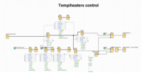
The Logo software looks like this


upload_2017-7-6_18-24-50-png.109177


Which basically has a night temp day temp and turns heaters off during WC and off for Initial pH boost whilst target [CO2] is reached.

It may look complicated, and the Logo software looks a bit 😱 but dont let it put you off. It wasnt that hard

Set Hydro heaters to 28 Degrees in the very unlikely event that something fails. If the PLC fails the Filter and one heater are still on as long as there is power.
 
This is a whole different world you're swimming in
Looks unreal but I'd never in a million years attempt it. My electrician on the other hand

Sent from my SM-G920F using Tapatalk
 
This is a whole different world you're swimming inemoji23.png

No its not- what one man can do so can another. pre sept 2016 never heard of Takashi Amano, Tom Barr, HC and as for injecting CO2 into water to grow plants 😵 as for PLC could of ment 'Please Leave Clean' to me :lol:
 
Back
Top