• You are viewing the forum as a Guest, please login (you can use your Facebook, Twitter, Google or Microsoft account to login) or register using this link: Log in or Sign Up

Arduino experts around?

Hi,

Do not see those BG board as a Programmer ? its just a couple of sockets and a voltage regulator as a mini dev board.

The USB ASP little boards do work, we programmed some Atmega328 chips direct, ie just the chip and a xtal, though cannot remember if we ever programmed in a bootloader, was a good few years ago.
Seems today there are more software options to run them, at the time we used some far east program that came with the stick., a bit of a learning curve as it needed details of which "fuses" to burn etc etc.🙄

It seems they like to overcomplicate things... At least for beginners, it is... I first did read the BG reviews on these boards and some say it's noo good and others say perfect if you know what you are doing... Thus I thought they seem to be good to go I'll figure it out and ordered them. They are Digispark clones and the chip needs a special bootloader to get recognized by the proper USB hub driver. The original Digispark seems to use the Micronucleus bootloader and USB drivers. But with these boards, I was curious and tried 2 different ones the Micronucleus en ATTiny85-default and still no go. Then we again have a run around to find the proper drivers, BG doesn't tell, people who know writing positive reviews probably don't tell for the nerdy fun of it. I don't know and actually don't care anymore...

The ATM chips don't require a bootloader at all to get programmed if the correct programmer is used. The first one I programmed worked straight of the bat without it. So I have no idea why they are developing and even cloning these things? And then sell it without the proper documentation? As if they just like to give people a run around for their money by selling silly crap. And indeed playing with bootloaders can mess up the fuses and render the chip useless. I think I messed one up but don't know yet.

But as you say, it's a learning curve... 🙂 Maybe that's why they are throwing curveballs, to keep us off the street.
 
I can say, I don’t understand an awful lot of this quest, my electronics career ended with my gcse’s, but im marvelling at your dedication to this project.

Think even @zozo will agree that he has had diffiucult and unusual route with his minature project, though starting off with the Arduino is normally a much easier experience.

If its something that interests you, for just £5 you can purchase, from this good uk seller, a starter clone Arduino board and run it with the free official software and countless online tutorials / examples.
Something to keep your mind active , lockdown or not 🙂

https://www.ebay.co.uk/itm/Arduino-...299808?hash=item4b2e3d0ba0:g:bmcAAOSwK~RaFdI3

Software
 
Think even @zozo will agree that he has had diffiucult and unusual route with his minature project
Haha, I certainly did, I went the hard way off the bat. I know it's not the best example to give for other newbie's. 😛 I just worked with what I had at hand and didn't want to sit around and wait on orders to arrive... Even tho I ordered a USBasp I got a little frustrated and impatient that I couldn't get the ESP to work as expected and simply didn't want to give in to that.
I guess that's the nutty troubleshooting pitbull mentality in me I developed in the 10 years I worked in the IT branch as SysAdmin.

And I must admit I'm also not entirely unfamiliar with electronics. I played with it for a few years as a teenager. Never made a hobby out of it because I actually was studying in a completely different direction. But it always kept intriguing my interest. I guess that's why ended up becoming a SysAdmin in the first place after working 25 years in the mechanical industry. We live in a very interesting era, the teen generation of the 1970s witnessed some crazy developments where mechanics and electronics where racing in more and more overlapping development. Looking at today's automobiles is the best example.
 
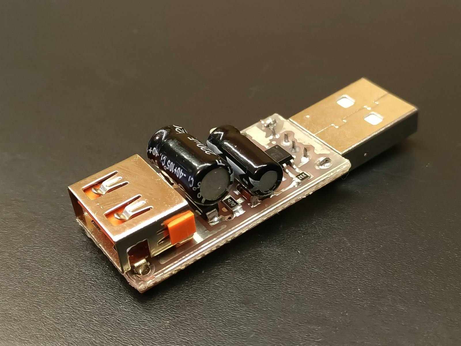
Haha, now the circuit is ready and hooked to the power bank at my friends' house and another nice issue I never thought about came up. :lol: Simply didn't know yet... But it seems those darn USB power banks are designed as chargers and not as constant voltage power supplies for low current applications. Thus this means each power bank requires its designed minimal draw current to stay switched on. If the current drops below a certain value the Bank closes and goes into standby.
Thus with the small +/- 70mA my circuit is pulling the Power Bank thinks it's switched on but doing nothing, thus goes in an auto power-off mode in a minute.

It seems to be a standard feature that all Power Banks have build-in. And to find one that doesn't is searching for the needle in the haystack or pay top dollar for specially designed experimental IoT Banks. Internet is littered with this question and complaint.

In my research, i found out that the only way to fool the power bank thinking it needs to stay on is to generate a pulse over an NPN transistor pulling a minimal load for a few millis before the build-in timer runs out and switches off. Most people use the NE555P chip for that in a separate circuit to pulse and pul the load.

Fortunately, I'm already using the ATtiny and this actually can do the same... So I had to edit my code to add a Pin and make this come High about every minute for 250 milliseconds to shortly pull the minimum load from the power bank to prevent it from switching off. 🤬:rage:

Here I made a small circuit diagram as to what it should be... Pin 2 runs the LEDs on/off for half a day over the 3904
schema.jpg

Pin 1 should pulse the minimum load over an NPN that I yet do not know so I left it blank with an X. Still need to get my hands on that specific power bank in question. From what I read I assume an extra 100mA once +/- every minute for a few milliseconds should fool it to stay switched on.

And extra power consumption, but no other way around it, it seems...
 
Last edited:
Nice circuit. It's a classic thing, think you have it all nice and working and then you plug it in and it doesn't work! However, Engineering a solution around it can also be quite exciting. Looks like a very elegant solution. You can also buy adaptors, but this wouldn't be as elegant.

Power Bank Keep Alive

If you find that changing the pin, for the keep alive circuit, interferes with other processor operations, you can use the built in clock on a pin that can operate independently of any code. If you have a simple program, then dipping out to toggle a pin every 250ms, might not be an issue, but can sometimes help. I've used this when running a stepper motor, the oscillator provides the pulses and the mircroprocessor is then free to run other buttons and sensors/LEDs etc.

Attiny Oscillator
 
Last edited:
Thanks... 🙂

Yes, I found this one and a few more of them Smarties trying to sell it, but looking a tad further I found the DIY diagram, etc.

Reading it I thought this I can do with the ATtiny no need for an extra chip etc, currently only using one pin still have 5 others left. So I looked up how to edit the code to get 1 extra pin pulsing over the internal millis time base first to see how that will go. Going to test how (long) that will run with this extra consumption added. Then I will find out how good the internal timebase is to keep the bank alive.

I had it running for a week on a phone charger and it doesn't seem to drift off in time that much. 🙂 But this could indeed be an issue with keeping the bank alive, yet no idea with the minimum current draw and the shut-off time sequence of that thing is. My mate said around a minute...
 
For those who like to see a simulation concept of this project visit Tinkercad via the link below.


This link is active for 336 hours counting down (Millis) from the time writing. 🙂 And actually, i have no idea if you need to subscribe to see the content. But if you do, no worries it's 100% free, no strings attached, and with a Google or Facebook account, it's done in a minute.

And Tinkercad is awesome, for a lot more design simulations than only this... Tinkercad rocks for many kinds of designs. Tho i guess you need to be a tad of a tech nerdy. ☺️
 
I'm finally done and have it working like a charm for now... 🙂 The diagram below...

schema.jpg
The Power bank has a build-in standby shut-off timer for 1 minute 58 seconds. Gave pin 1 from the Attiny via a npn transistor a 55 Ohm 1 Watt resistor and a small green 20mA LED resulting in +/- 120mA total dummy load. This comes on for 1 second every 110 seconds and a little green LED blinks. That is 8 seconds before the Power Bank shuts off and resets the shutdown timer to 0 again and about enough to keep it on 24/7.

Now it's waiting to see how long that power bank will run this circuit... If calculated correctly and if the Bank specs are accurate it should run at least a month. 🙂
 
It's done and rocking and rolling like a charm... 🙂

I decided to keep the actual PCB in view to add some intrigue to the project. The Old Cigarbox contains the battery. The copper coil on the PCB is an ornamental fake doing nothing other than look nice. I kinda liked to add it, because it also adds intrigue and adds to the overall steampunk style.
IMG_20210402_144413303.jpg

With all 3 LEDs at full power 60mA, it ran at the first for 26 full days... Then I looked in the dark and dimmed the LEDs to 8mA each and it still is light enough... That is 24mA total and 36mA less consumption. Thus most likely it must run a lot longer than 26 days like this on a full battery.

IMG_20210402_144446444.jpg

Backside view, with On/Off switch and a USB-A flat cable...
IMG_20210402_144514946.jpg

Top view of the PCB, with the blink, LED on... 🙂 I'm planning to paint the PCB silver colour and put some brass and bronze colour on the components with enamel model paint to keep all in the same old fashion Edison style...
IMG_20210402_144732518.jpg

And the power bank in the Cigar Box...
IMG_20210402_144828276.jpg
😀 No idea if this is the first Battery powered ATTiny Terrarium?

Technically finished and approved, aesthetically still a little work to do... :thumbup: I'll test run it for another month or so before I start painting.

For those interested, this is the final circuit... Completely wrong drawn by conventions, but I guess it does the job...
schema.jpg
 
Last edited:
:nailbiting:

Oh, I have the same one like this. Critical when I wanted to charge my cell phone or tablet quickly. Have had different advice from TSA here on whether I can take it onboard a plane, so have used it only if traveling by car, bus, or train. Easily charges cell phone 3-4 times before requiring a recharge. The battery holds enough juice for me to use it all week. It may take a few hrs to charge the device completely but it’s 100% worth it
 
Back
Top