• You are viewing the forum as a Guest, please login (you can use your Facebook, Twitter, Google or Microsoft account to login) or register using this link: Log in or Sign Up

Arduino experts around?

Yeah cool, it is an awesome little project 🙂

Have you seen the candles that have a built-in timer with an LED?

Amazon product ASIN B06XBWNJZC
I have one, and it turns on for 8 hours every day at the same time, and the batteries on it last forever, I am pretty sure you could also take one of those apart and build that little system you pictured above! Might just have to increase the size of the LED if needed!

Bonus: Remote controlled!

Thanks Paulo, yet didn't seen these things... Absolutely worth to take one apart and look inside... All tho i'm not sure if the led is powerful enough... 🙂 A regular white coloured LED giving 12000mcd consumes 20mAh, 1 didn't cut it, currently i'm using 3 (36000mcd) and this seems to grow mosses nicely... I haven't tried 2 yet, but assume it works as well that would be 40mAh consumption. A regular AA provides if its a high end 3000mAh / 40mAh it runs flat in 75 hours.
 
Will keep an eye on this, I am more used to Raspberry Pies 😉
 
I've tried this, but it wasn't a real success... 😂


Haha, love the little generator.

I saw the bit about the ATTINY85, they are great little microcontrollers. I did a similar project for a dummy alarm box with warning LEDs. If you use a crystal on the microcontroller, it will keep pretty accurate time. I programmed it so that once it was powered on, it would flash LED's for 8 hours, then put itself into sleep mode for 16hours, then on again for 8. kept time very well and battery lasted for ages. I had the advantage that the LEDs were flashing, not the constant on in your application. But as a simple elegant solution, the ATTINY85+some transistors gets my vote!
 
Found the perfect code to do the job... And it actually is just a small snippet...

Original

Mine
Knipsel.JPG

Had to do quite some fiddling to find the way to make it work right... The initial script started always with a LOW (LED Off).
Whatever I changed that looked obvious to me I couldn't get it to start at power up with a HIGH (LED on). I guess this is because all similar scripts I found counts milliseconds from an Unsigned Long previousMillis starting at 0 and then simply always starts with a LOW regardless if the HIGHs and LOWs in the script are changed it only gets a HIGH when it reached the currentMillis set value. :what: Then if it's powered on its off and you need to wait 12 hours for the lights to come on.

Searched the internet and it seems I wasn't the only one complaining about this code working in reverse but couldn't find a simple solution... And at one point I had an enlighting moment and thought if it counts from 0 to + then can it also count from - to 0?


😛 Lo and behold and it can and it does... I changed previousMillis from 0 to Minus TWELVE_HOURS and it works like a charm it now starts at power-up with the LED On and switches Off when 12 hours are counted down. Huh? Up. Whatever!? :thumbup:
 
Last edited:
For those yet far from the expert like me, but have a basic understanding of electronics and a little coding experience.
And you like to give it a go, to play with the NodeMCU ESP8266 to create a timer switch relais to switch on your lights via a web server interface on you PC or mobile phone.

Then have a look at this free to use ESP8266_TimerPowerSwitch code at github. It works like a charm with a little code tinkering to get the correct UTC Offset for realtime display on the server.

The straight forward webserver dash looks like this in your browser...

Home
Knipsel.JPG
Settings
Knipsel1.JPG


If you are yet not really familiar with creating electronic circuits then hop to <TinkerCad>. It's also free after you created an account with your Google or Facebook account. You can create simple circuits with all sorts of components and test them out, it also has an Arduino platform with the IDE tool to create code and test both, circuit and code in a virtual simulation. Very handy to find out if you are on the right track without the need for purchasing any components. 🙂

I played a little with the ATTiny microprocessor circuit I intent to use on one of my projects as said to switch a few LEDs on and off with a 12-hour interval with the lowest power consumption possible. And it looks like this.
Knipsel3.JPG
This worked exactly as intended and it's ready to be built in realtime...

It's really fun to play with and very educative... Awesome tool for noobs like me... And if not for you maybe your kids will love it, ThinkerCad has a lot more to offer then circuits only.

:thumbup:
 
Last edited:
Hi,

Good to hear you have got it working ok, but there is a bit of a flaw in your hardware in terms of battery life, if it is as shown above.

The Linear 3v3 regulators use at lot of current that they waste as heat converting the 9v to 3v3 , probably more that the rest of your circuit including the led.

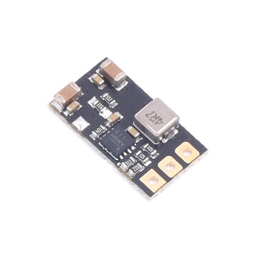
To give a much better battery life use one of these little £1 Buck Converter modules, you have to set it to 3v3 with the little trimmer and a volt meter before connecting in circuit, but once done they are around 90% efficient.

Would think it will increase your battery run time by 50 to 100%.


000439.jpg
 
Hi,

Good to hear you have got it working ok, but there is a bit of a flaw in your hardware in terms of battery life, if it is as shown above.

The Linear 3v3 regulators use at lot of current that they waste as heat converting the 9v to 3v3 , probably more that the rest of your circuit including the led.

To give a much better battery life use one of these little £1 Buck Converter modules, you have to set it to 3v3 with the little trimmer and a volt meter before connecting in circuit, but once done they are around 90% efficient.

Would think it will increase your battery run time by 50 to 100%.


View attachment 162417

Thank you for your reply... 🙂 I knew the Mosfet and 9-volt battery as shown in the circuit isn't the one I should use, but it's an option limitation in TinkerCad. It's the only 3.3 voltage regulator I could choose as a listed example component that in principle practice works the same.

I actually already have the buck converter you link to...

But, I choose to use the TO92 <HT7533> regulator instead since the complete circuit I intend to build is only consuming about 70mA total. And the power supply will be a 5-volt power bank.
 
Last edited:
Hi.

Afraid I was incorrect , just did a test on the two types of regs with a 5ma led load and there is little current difference between the two, seems the buck converters must come into their own at higher current.
Have actually replaced my projects hotish T220 regulators with the bucks and they and the transformer run cool by comparison, so must be saving power.

So now you are into programming ,when is the new tank controller due out ....😁
 
So now you are into programming ,when is the new tank controller due out

I did some VBS programming for almost a decade ago in my IT years to automate some computer tasks. Now VBS is ancient and discontinued because it's too rough around the edges. But under the hood it has some similarities with LUA, so that comes in handy to figure out what this basically does and pick some of it back up a bit... Now I'm far from a programmer and don't have the ambition to become one and reinvent the wheel. In most cases, all simple tasks it can do is already out there and done before by others. I'm more of a script kiddie that conveniently searches the net for open-source example snippets I can copy/paste and or edit it with minor changes to make it work for my needs.

It's an old Dutch motto. "It is better to steal something good then to invent something bad" 🥳🤭

By the same motto, I build simple electronic circuits, basically, I know or if not I find out how to connect things to make it work. How it exactly works from the inside out I don't really need to know to learn and remember all of it in detail.
I guess that's the reason why I know a little (basics) of a lot of interests and meanwhile running around like a chicken without a head never found the time nor ambition to become an expert in anything.

Some experts I know call this ADHD... 🤔 (But IMHO it's a or their disorder to put personalities in boxes)

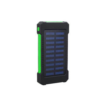
So I really don't know if I ever build a complete tank controller... For now, my brain fart is I want an extremely low power consumption battery powered light switch for a mini terrarium. 🙂 Basically, it will be ready on a breadboard somewhere next week, to test it how long it actually will run on that power bank. The aim or expectation is at least 30 days, but this still is a theory... If it does that +/- than I will solder it to a PCB and use it.

After this, I will most likely switch to another brain fart again, usually in an opposite direction. Backing bread maybe...
 
Last edited:
Hi,
You might want to look at the LP2950 or similar Low Drop out 100ma regulators or the little Buck/Boost modules to squeeze the last bit of power out of the battery.

Mini DC DC 3V-15V To 3.3V/5V/12V Automatic Buck Boost Module Converter UP/Down | eBay

Yes, most folk start off programming the way you have, but soon find they are modifying those routines to suit their particular needs which in turns expands your abilities and soon end up writing most of your own work, can be addictive !
 
Thank you! 🙂 I have a couple of these at home in 3.3 and 5 volt
And they actually are rather tiny and seem to be pretty sufficient, but still draw relatively high current on their own.

After doing some research on low power applications I found an expert video tutorial on building the best 3.3v voltage regulator. The video is actually about ESP boards in deep sleep, in this case, I only focussed on the regulator explanation.


High current is indeed very relative it's from mA to µA but most regulators as recommended draw more current on their own than the device its powering. And i do not need to draw 2A maybe 70mA total.

With something like an HT7533 or similar. In the datasheet of this regulator, it is recommended to use 10µf capacitors between Vin and Vout and Gr to stabilize it and prevent voltage drops so the device doesn't crash. He explained and showed that the recommended 10µf in the Vout still has a rather high current leakage making the regulator still a rather unstable drop more voltage and draw more current. That it's best to replace this Vout capacitor with a beefier 1000µf capacitor to achieve more stability with only 0.1v voltage drop and 24µA the regulator itself draws from the battery. So I decided to go this route instead. In theory, it seems to be much lower consumption and next to that it's also a lot cheaper, the 3.3v regulator and 2 capacitors together are only € 0.70. I thought I can't go wrong with this. 🙂

Yes, most folk start off programming the way you have, but soon find they are modifying those routines to suit their particular needs which in turns expands your abilities and soon end up writing most of your own work, can be addictive !

That's true, in my IT years i really liked to play with VBS programming, used it quite a lot to make life easier at work so it made sense. But then I dropped out that line of work went another direction and kinda forgot about it again. It could very well be I go on with LUA if I find any more future purpose for it. Microcontrollers are indeed very interesting little things. Who knows!? But for now, all I can think of for now is already invented and cheaply available. 🙂

Yesterday I found Blynk you also might like... Possibilities are indeed endless

:thumbup:
 
Last edited:
On a side note, for those into DIY and still using the bulky Timer Switches analogue or digital but interested in more convenience.
Have a look at the Sonoff products... 🙂
 
Hi,

Just one point about that video, he was talking about regulators like the 1A AMS1117 and the 0.25A HT7333, but you mention the HT7533 at 0.1A.
Thats is only available in SMD , which might be a problem soldering for you ? if so the LP2905 has similar low current parameters but T092 packaging.

With either of those 100ma regs, 1000uf across Vin is ok, but not sure if 1000uf across its Vout will work safely , a discharged 1000uf will initially present as a short to the regulator and might exceed its 100ma limit ??
Perhaps 220uf or 330uf more suitable for such a low current.

Regarding the Buck modules, the one I last referred to is a Buck Boost module that intially acts like a voltage regulator, but when the battery drops to around 3v5 it would normally loose its 3v3 regulation, but the Boost part will allow it to still produce 3v3 even though the battery voltage has dropped to say 2v.

Yes, did try a simple test with Blynk when we first got the ESP boards, but was about to put a post up on the electronic forums to see if Bylnk or any others are the best to use, not just from a coding point of view but more in terms of will they be available in the future, a bit like other online services where a couple of years later they withdraw things and everyone has to change or pay high charges.

Those Sonoff devices do seem good and popular , though a bit old fashioned there, why do we want to turn things on and off from a mobile phone ?
Same when it comes the fish tank, surely your system should be designed to control things, so why would you want to override that remotely ?
eg. We would not want to change dosing parameters and not be around to properly observe the effects.
 
the HT7533 at 0.1A.
Thats is only available in SMD

I have it in TO92 model, it actually was the only 3.3 regulator available at that shop. Got it in the mail this afternoon and is already running fine so far. Still waiting on the ATTiny to arrive.
IMG_20210209_184805797.jpg
I didn't think of a capacitor discharge and fry the regulator!? Why would this happen? But if so and the risk is high, it might indeed be good to replace it. Not going to die over a few µA. 🙂 All tho it already seems to discharge over the LEDs when its switched off by the looks of it. The LEDs fade off.

Good point on the buck converter... :thumbup: Something to keep in mind depending on how the HT7533 works out.

Those Sonoff devices do seem good and popular , though a bit old fashioned there
Lol, yes things go crazy fast these days with electronics, you buy it walk out the door and you're about old fashion before you're on the street.

why do we want to turn things on and off from a mobile phone ?
Also a good question one should answer for himself... I happen to have a few occasions I find it handy... One happens to be the lights from one tank where the power plug and the timer switch in it is behind a huge jungle of plants and pots I need to move to get to it. The next time I'll need to be there I'll definitively be going to replace it with a Sonoff I already have laying around. 🙂 For example, next time when we need to reset the clock to summertime. 🙂 And thereafter no more moving plants and pots and reset it manually. The other one is switching some lights on in the garden without the need for opening the door, going out and plug them in and visa versa. Well, I guess having multiple remote controls laying around is even more old fashion and less convenient than 1 mobile phone. Or install MemuPlay and do it via the PC.

For the rest indeed, I'm personally also not font on totally automating fishtanks I rather keep my hands on it... Also not into auto dozing fert or food... Not my intention I like this also the old fashion way.
 
Hi! I have also started to mess around with arduino and I was wondering if there's a reason you don't use real time clock (RTC)?
 
Hi! I have also started to mess around with arduino and I was wondering if there's a reason you don't use real time clock (RTC)?

Yes, my aim is to make a low power application that runs as long as possible on a battery/power bank. And I have 60mA LEDs that need to be turned on 12 hours a day.

I did think of doing this with the help of an RTC, but in the end only means more power consumption. Then what good is an RTC if you can't read it real-time? And if not updated regularly it will have the same deviation in the microcontroller simply counting down milliseconds. Then updating/syncing an RTC would require an NTP connection. Again a relatively high consumption source to build that around it.

To undress it from all actually unnecessary bells and whistles that consume power. I thought to take a simple blink sketch put this in a microcontroller and make it turn the LED on at startup then countdown 12 hours to turn it off and back on 12 hours later. With an indefinite loop.

The moment the microcontroller gets turned on it turns on the LEDs and it starts counting down and does this with the very same milliseconds and clock speed as it would run the RTC. There would be no difference, in this case, an RTC has no added value. If there would be a 15-minute time shift in a month time then a hard reset would be enough to start over again with a fresh count. This actually will happen anyway since it runs on battery and this will need to be replaced. If my calculations are correct about every 45 days. 🙂
 
Hi! I have also started to mess around with arduino and I was wondering if there's a reason you don't use real time clock (RTC)?

Just to add, yes agree with zozo, it's another overhead that you have to manage with power, both processer and energy. For most simple delay projects, the internal timer suffices.

The moment the microcontroller gets turned on it turns on the LEDs and it starts counting down and does this with the very same milliseconds and clock speed as it would run the RTC. There would be no difference, in this case, an RTC has no added value. If there would be a 15-minute time shift in a month time then a hard reset would be enough to start over again with a fresh count. This actually will happen anyway since it runs on battery and this will need to be replaced. If my calculations are correct about every 45 days
If you use an external crystal on the ATTINY microcontroller (most arduino's have these built in) rather than the internal clock, you might find it keeps time better.
 
Back
Top