I'm in the process of building my high tech Iwagumi tank (link) and want to add a controller with the following functions:
1.) Temperature probe: cuts off the heater and light if it fails in the on position, turns on chiller above set temperature.
2.) Auto top-off system with 2 sensors.
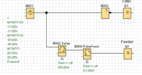
3.) Programmable feeder, which turns of the canister filter when feeding,
4.) Programmable module that turns CO2 on or off based on PH probe, and based on timer (off at night). I have a Milwaukee controller but would prefer all from same brand.
5.) Alarms should be send via text / email / app to cell phone.
6.) App for remote monitoring and access would be nice.
Did anybody try one of the reef tank controllers (Neptune Apex, Digital Aquatics ReefKeeper, etc.) in a fresh water setup? Any suggestions?
1.) Temperature probe: cuts off the heater and light if it fails in the on position, turns on chiller above set temperature.
2.) Auto top-off system with 2 sensors.
3.) Programmable feeder, which turns of the canister filter when feeding,
4.) Programmable module that turns CO2 on or off based on PH probe, and based on timer (off at night). I have a Milwaukee controller but would prefer all from same brand.
5.) Alarms should be send via text / email / app to cell phone.
6.) App for remote monitoring and access would be nice.
Did anybody try one of the reef tank controllers (Neptune Apex, Digital Aquatics ReefKeeper, etc.) in a fresh water setup? Any suggestions?
") rolleyes
rolleyes
 never an issue except you have to pay for your own postage.