Parablennius
Member
One for any electrical wizards out there. I’d like to replace the control box that is wired between the pump and power supply ( 20 presses from full to minimum ) from a TMC12V DC brushless pump with a rheostat. This would be simple with a conventional motor but brushless dc motors have 3 wires which I understand they need. So, is this doable? Stepdown states output of 12VDC @ I AMP. Quite happy/ competent with soldering etc. TIA . Steve
Last edited:
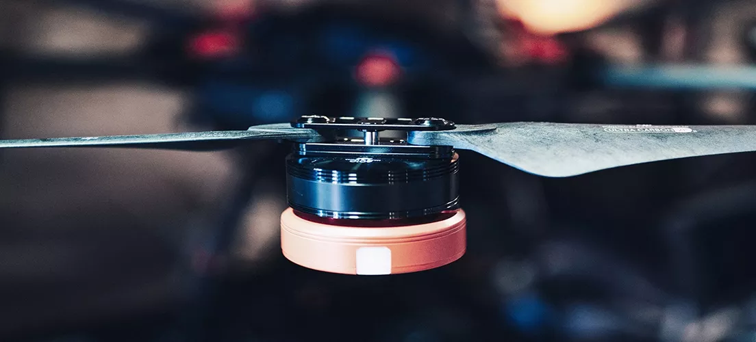


") Maybe this helps.
Maybe this helps.