dino21
Member
Hi,
Do not see those BG board as a Programmer ? its just a couple of sockets and a voltage regulator as a mini dev board.
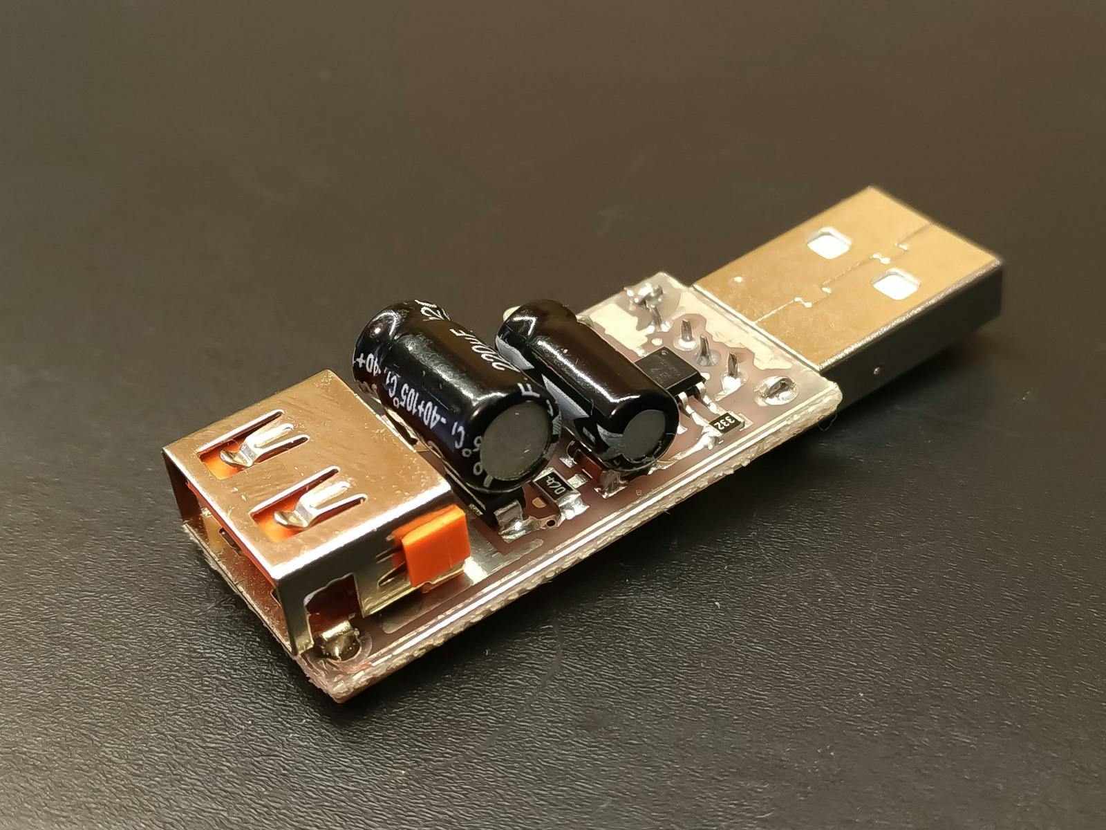
The USB ASP little boards do work, we programmed some Atmega328 chips direct, ie just the chip and a xtal, though cannot remember if we ever programmed in a bootloader, was a good few years ago.
Seems today there are more software options to run them, at the time we used some far east program that came with the stick., a bit of a learning curve as it needed details of which "fuses" to burn etc etc.
Do not see those BG board as a Programmer ? its just a couple of sockets and a voltage regulator as a mini dev board.
The USB ASP little boards do work, we programmed some Atmega328 chips direct, ie just the chip and a xtal, though cannot remember if we ever programmed in a bootloader, was a good few years ago.
Seems today there are more software options to run them, at the time we used some far east program that came with the stick., a bit of a learning curve as it needed details of which "fuses" to burn etc etc.